Main Menu
- Home
- Product Finder
- Calibration Systems
- Calibration Services
- Digital Sensing
- Industrial Vibration Calibration
- Modal and Vibration Testing
- Non-Destructive Testing
- Sound & Vibration Rental Program
- Learn
- About Us
- Contact Us
As you may remember from your studies, ideal sensors provide straight line performance. That is to say, they treat amplitudes proportionally (straight line linearity), frequencies of interest the same (flat amplitude frequency response), and do not appreciably delay the signal (flat phase frequency response). Hence, the frequency response output plot from an accelerometer and on a calibration system should be a flat line. In the real world, however, things are not perfect...
Just like people, sensors and data acquisitions systems and measurement processes are all imperfect. There are ranges where the behavior is near ideal, and there are areas where it is not. Again, like people, the imperfections or anomalies tend to show at the extremes. In the accelerometer world, the imperfections show up as bumps or glitches that deviate from a straight line on the frequency response function. The anomalies are typically at low frequencies or high frequencies. Seasoned calibration professionals use these indications as clues to tracking problems in either person, performance or process.
If glitches or a premature roll-off in the response show up at low frequencies, it is normally the result of one of two causes. A rapid roll-off at low frequency is usually indicative of a short discharge time constant (DTC) of either the sensor or the coupling/conditioning circuit. If this causes the sensor to be out of specification in the low end of amplitude frequency response, the sensor is usually checked for specific DTC via flip or drop method (link to DTC article). The other common cause of frequency response anomalies at low frequency is due to improper cable strain relief. When dealing with the longer displacements at very low frequencies it is imperative to ensure that a flexible cable is used and that a sufficient service loop of cable is tied off to allow cable flex without straining the accelerometer on its mount. When lengths of cable are not secured with strain relief loops and are allowed to drape from the calibration exciter, the strain forces can cause the accelerometer to have unusual outputs such as rising amplitude at low frequency (where we expect amplitude to normally begin to roll off at low frequency due to the sensing system DTC) or glitches in the low frequency (<10 hz) amplitude response.
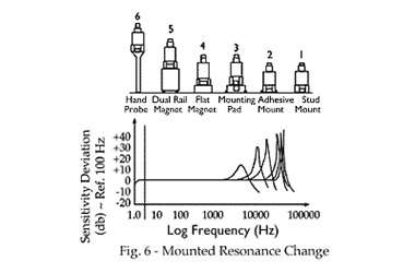 In the high frequency ranges there may be other causes which will make an accelerometer’s response deviate from the ideal straight line. The first, and by far the most common, is any number of variations relating to mounting.
Intimate contact with the moving structure’s mounting surface is paramount as frequencies approach the upper end of the accelerometers’ specified amplitude frequency response. Diligently following the sensor manufacturer’s guidelines for mounting torque and type of mounting stud is the first item to check. For example, some mounting studs have a shoulder to prevent it from bottoming out in the accelerometer so check that the accelerometer has a counter bore to accept the shoulder. Otherwise you will be measuring the elasticity of the mounting stud. Next, the calibration mounting surface should be free of nicks or scratches and be prepared with a very light coating of grease (typically supplied with precision calibration systems) to enhance the motion transmissibility at higher frequencies. This is most often the case for amplitude frequencies responses that exhibit a steady rise out of specification failing factory specification conformance by a few percent. If glitches show up at a specific frequency, the next item to check is transverse motion of the calibration exciter. If the calibration exciter employs a flexure based design to support the armature, it is common that at the resonant frequencies of the armature structure, the exciter is actually moving more in the lateral direction than it is in the primary direction of excitation. The glitches are an artifact of the system measuring this motion through the small cross axis sensitivity of the accelerometer under test.
 This problem was addressed in the latest revision of the ISO16063-21 standard on accelerometer calibration by including guidelines on the acceptable levels for shaker transverse motion. As a result, most precision calibration systems now include low transverse air bearing exciters as the standard option. As a “band-aid” to existing operation of calibration systems, the measured exciter transverse motion should be minimized. This is accomplished by aligning the minimum of the sensor cross axis sensitivity with the shaker transverse motion. In practice, the accelerometer can be rotated a few degrees at a time until the minimum of the transverse sensitivity is aligned as indicated by the minimum glitch size in the output. This is typically an iterative process and not very time efficient. This technique rarely eliminates the glitch completely. It also has limited reproducibility as cabling also affects the shaker resonance frequency and motion.
A final anomaly in high frequency response can be caused by damage to the accelerometer's internal sensing element. This type of damage can be screened for with a very high frequency sweep up to 50 kHz which will show the sensors mounted resonance of the crystal/mass element structure. This type of functionality can be found in modern precision calibration air bearing exciters.
From these various examples we can see that ideal behavior is often elusive. Flat lines may be boring to doctors and economists but to calibration professionals they are simply elegant. As always, if you have any questions or concerns with calibration, please don’t hesitate to contact us directly.