Main Menu
- Home
- Product Finder
- Calibration Systems
- Calibration Services
- Digital Sensing
- Industrial Vibration Calibration
- Modal and Vibration Testing
- Non-Destructive Testing
- Sound & Vibration Rental Program
- Learn
- About Us
- Contact Us
Proper mounting techniques are essential to calibrate all accelerometers. The mounted resonance of a vibration sensor directly affects the practical upper limit of the flat frequency response of that sensor. Cleanliness; surface finish and flatness; the light use of a coupling fluid (like silicone grease) between the accelerometer base and the mounting surface; and the right amount of torque (if stud mounted) as recommended by the sensor manufacturer; these all play a significant role when calibrating an accelerometer as we covered in a previous newsletter article entitled, "Why Proper Mounting is Essential to Calibration."
The good news for metrology is that most accelerometer designs are built symmetrically to allow: 1. The sensing element to be directly in line with the axis of calibration excitation, and 2. Approximate equal distribution of the sensor mass around its center of gravity to avoid off center loading and resultant rocking of the exciter armature. These two key elements help to ensure purely uniaxial calibration motion aligned with the sensing element. As such, it is relatively easy and straightforward to calibrate a single axis sensor or a cubic shaped triaxial accelerometer (as the sensor can typically be flipped and centered on each of its X, Y, Z, directions).
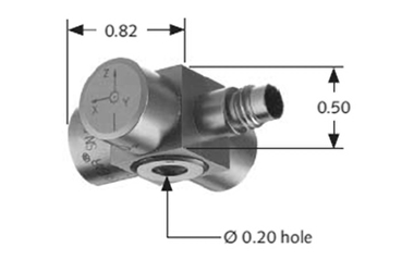
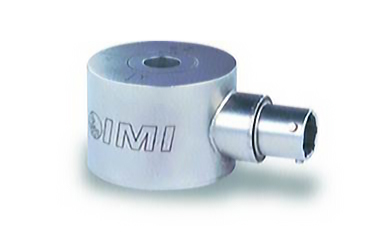 Now, how do you approach calibrating awkwardly-shaped triaxial accelerometers such as the ones shown in the following pictures?
First, start with the easy axis! As can be seen in these pictures, the accelerometer's through-hole design offers a specific, easy method for mounting the sensor on its Z-axis direction. For this axis the same mounting recommendations as before apply (surface cleanliness, grease mounting, torque, etc). While calibrating this axis may still pose a challenge -- likely due to rocking motion induced from an off-centered mass load - the Z-axis should still provide a good benchmark for how the other two axes will behave. Most models will be similar but have a more conservative specification on the axis that is not capable of being mounted in the ideal back-to-back method.
 So, now what? How do we calibrate the other two axes since they are obviously not designed to be mounted in such a configuration?
The answer may be a little tricky. A mounting adaptor is almost always required and no matter what you do, the material type, size and shape of the mounting adaptor will play a role in the accelerometer frequency response calibration results.
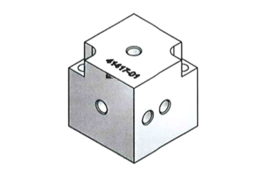 For example, a mounting block such as the one shown in Figure 3 is typically used for calibrating the X- and Y-axes of the accelerometer shown in Figure 1, which is necessary to meet the frequency response up to 5000 Hz (±3 dB). Care must still be taken by applying grease to the mounting surfaces and by properly relieving the sensor cable strain. When designing such an adaptor, attention must be paid to keep the center of gravity as close to the center of the shaker as possible. Therefore, a hefty counter balance mass is added on the other side of the mounting block during calibration (thus minimizing the risk of dynamic moments inducing shaker transverse and rocking motion).
In the end, whenever you need to calibrate such an awkwardly-shaped triaxial accelerometer, do not hesitate to contact the original sensor manufacturer if there isn’t an obvious way to mount the sensor in each of its sensing directions. It may be the only way to successfully complete your task.