Main Menu
- Home
- Product Finder
- Calibration Systems
- Calibration Services
- Digital Sensing
- Industrial Vibration Calibration
- Modal and Vibration Testing
- Non-Destructive Testing
- Sound & Vibration Rental Program
- Learn
- About Us
- Contact Us
“How can I reduce the uncertainty of my calibration?”
Before diving into this month's article, I thought it would be prudent to review the terminology for different sensors used in back-to-back accelerometer calibrations. For the purposes of this article, I will refer to the sensor that will ultimately be calibrated and used in the field as the "Sensor Under Test" or SUT. This sensor is sometimes called the "Device Under Test" or DUT. The device that calibrates the SUT-level sensor will be called the "working standard" — in conversation "reference sensor" is typically used interchangeably. Above this type of sensor in the calibration chain is a "transfer standard" or "gold standard." This is a sensor that has been primary calibrated and serves to calibrate the working standard(s) (see Figure 1). Now that we have common terminology, we can address the aforementioned question: "How can I reduce the uncertainty of my calibration?"
There are two common methods that can drastically reduce the uncertainty of a SUT calibration. Often, the single highest uncertainty contributor in the calibration of a test sensor is the contribution from the calibration of the working standard. The working standard is typically calibrated through either secondary calibration via a transfer standard (back-to-back calibration of the reference), or directly via laser primary calibration. These traceability chains are depicted in Figure 1 below. You can notice that by directly primary calibrating the working standard, you can shorten the traceability chain, which leads to a lower overall uncertainty in the SUT calibration.
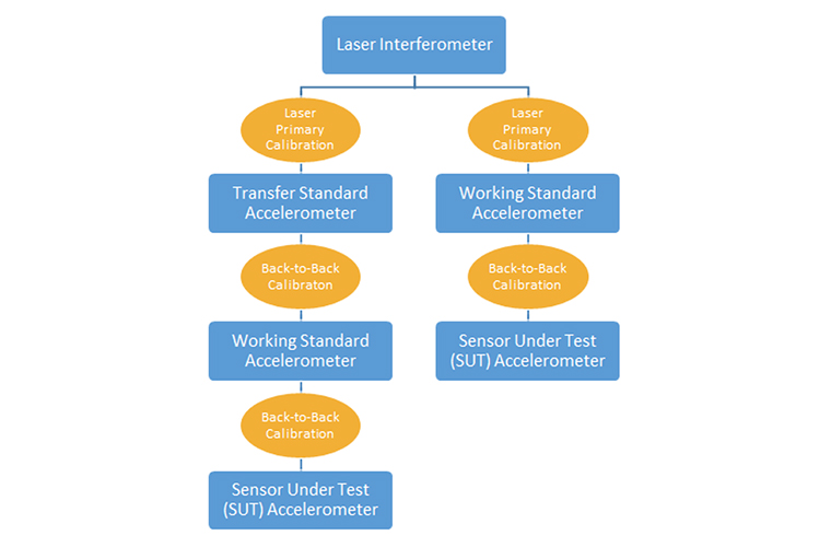
Figure 1: Calibration Traceability Hierarchy With and Without Transfer Standard
The second (and potentially large) source of uncertainty in calibration of the SUT is how the working standard calibration data is used in the calculation of the SUT sensitivity. In back-to-back calibration systems, the equation that defines the sensitivity of the SUT is often presented as follows:
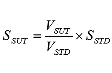
Where:
SSUT= The sensitivity of the SUT
SSTD= The sensitivity of the Standard sensor
VSUT= The voltage output from the SUT
VSTD= The voltage output from the Standard sensor
The voltage ratio are fixed numbers that are the electrical result of the shaker’s mechanical motion, but what about the sensitivity of the Standard sensor (SSTD)? The calibration systems of some labs use a single value for SSTD, often the value at reference frequency. The problem with this is that any deviation from this reference sensitivity as the result of the working standard sensor’s frequency response will be a direct error influence on the measurement.
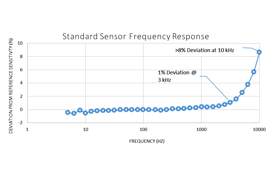
If we take a look at the typical frequency response plot of a Standard sensor below, we can see that if only the reference frequency’s sensitivity is used in the SUT sensitivity calculation, there would be a 1% error in the measurement at 3 kHz rising up to more than 8% at 10 kHz.
There are a couple of solutions to this issue. The first would be to select a reference sensor with a very high mounted resonant frequency. This could reduce the severity of the error at higher frequencies but the error would still be present. There will always be a physical constraint in the design of a reference sensor that does not allow for an infinitely high mounted resonant frequency; there will always be some level of error when using a single standard sensitivity. The full solution is to use a different standard sensitivity depending on the frequency under test. Using a dynamic sensitivity for the standard eliminates frequency response error and can extend the useable range of a calibration system. Most modern calibration systems employ the use of a multi-point standard sensitivity file, often with some form of interpolation between data points to produce an infinite resolution of reference.