Main Menu
- Home
- Product Finder
- Calibration Systems
- Calibration Services
- Digital Sensing
- Industrial Vibration Calibration
- Modal and Vibration Testing
- Non-Destructive Testing
- Sound & Vibration Rental Program
- Learn
- About Us
- Contact Us
DC response accelerometers are vibration sensors capable of measuring a DC, or 0 Hz, response. The most common types of DC response accelerometers are based upon a variable resistive or capacitive design. Generally termed piezoresistive (PR) or variable capacitive (VC) within the measurement and instrumentation industry, these transducers cover a wide range of applications, from expensive precision transducers for military and defense applications, to very inexpensive MEMS transducers built on electronic component packages for smartphones and automobile airbag deployment sensors.
PR accelerometers are designed with sensing elements that change their electrical resistance due to an applied mechanical stress. They utilize piezoresistive material, typically metal strain gauge or silicon resistors, in a Wheatstone Bridge configuration, and require a fixed DC excitation voltage for power. The sensing elements are typically bonded to a cantilever beam that bends in response to acceleration, thus causing a change in resistance. Since this varying resistance is sensitive to a steady state acceleration, such as its orientation within Earth’s gravitational field, PR accelerometers provide a true DC response.
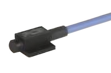
Piezoresistive Accelerometer
VC accelerometers sense a change in electrical capacitance, with respect to accelerations, to vary the output of an energized circuit. Typically, the sensing element design consists of two parallel plate capacitors acting in a differential mode. These capacitors operate in a bridge circuit, along with two fixed capacitors, and alter peak voltage generated by an oscillator when the structure is subject to acceleration. Circuits capture the peak voltage, which is fed into a summing amplifier that processes the final analog output voltage signal for measurement.
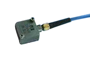
VC Accelerometer
Both PR and VC accelerometers typically operate on three- or four-wire excitation power; one pair of leads for signal/ground and another pair for power/ground on the four-wire versions and a shared ground on the three-wire versions. The excitation voltage is a fixed DC voltage, commonly set across a specified range (see manufacturer’s specification sheet for the unit’s model number), and can affect the unit under test's sensitivity. As a result, when calibrating these types of transducers, it is very important to use a reliable, calibrated DC power supply, and note the excitation voltage on the calibration certificate paperwork.
A significant advantage of these types of sensor designs – that is, transducers that are truly responsive to DC acceleration – is that they are inherently self-calibrating, at least at 0 Hz. Since the transducer is sensitive to DC acceleration, they are sensitive to a “flip” within Earth’s gravitational field. Therefore, if you have a flat, solid surface, the sensor can be flipped from one side to the other, (a 180 degree flip from base to top) which is equivalent to a 2 g step change. By measuring the DC voltage output change, and dividing by 2 g, you can calculate the unit sensitivity (in V/g or mV/g) at 0 Hz and validate its DC response performance. Furthermore, the DC offset voltage may also be measured in the same manner by finding the voltage "mid-point" between the 1 g and -1 g excitation.
A full calibration would generally also include a frequency response calibration, traditionally run as a stepped sine sweep on an electrodynamic air-bearing calibration grade shaker. This methodology is typically a secondary calibration, commonly termed “back-to-back,” referenced to a transfer standard of “piggyback” design. It is important to note that the frequency range of the calibration is dependent upon the shaker performance characteristics. The industry standard wide frequency air-bearing calibration shakers may cover a range of 5 Hz to 15 or 20 kHz. These shakers generally have excellent transverse motion characteristics, but also have a short stroke (commonly around 10 mm). This short stroke prevents adequate calibration at frequencies below 5 Hz due to the lack of reasonable acceleration levels at declining frequencies. For calibration from 5 Hz down to as low as 0.1 Hz, it is important to use a specialized long stroke shaker (commonly up to 0.25 meter of stroke) to allow the calibration technician to generate suitable acceleration levels at these ultra-low frequencies. This may be especially important when calibrating DC response accelerometers intended to measure very low frequencies, for applications such as automotive ride quality or civil infrastructure dynamics. Regardless of which shaker designs are available during calibration, it is excellent practice to compare the lowest frequency dynamically calibrated against the DC response from a flip test.
-product-1.jpg?Status=Master&sfvrsn=2daa56e5_0)
Calibration Air Bearing Shaker

Low Frequency Long Stroke Calibration Shaker
Depending upon the specified application of the DC accelerometer, a full calibration may also include a shock calibration. One common use of DC responding accelerometers is measurement of high g shock and blast events. For these sensor designs, best practice is to perform a shock calibration along with a frequency response. There are several types of shock calibration devices that involve a linearity calibration across a wide amplitude range, typically generated via an impact of some sort. Pendulum devices, pneumatically controlled projectile impacts, and Hopkinson bar shock waves are commonly used to generate impulses ranging from 100s of g’s to 100s of thousands of g’s.
-product-2.jpg?Status=Master&sfvrsn=a0af64fa_0)
Pneumatic Shock Calibration System
Finally, a common “calibration” technique associated with strain-based DC accelerometers is termed shunt calibration. Shunt calibration is the known, electrical unbalancing of a strain gauge Wheatstone Bridge, mentioned earlier in this article. This is accomplished by means of placing a fixed resistor across one leg of the bridge, or “shunting” it. By utilizing this technique, the gain of the signal conditioner paired with the strain-based DC sensor is validated, without exposing the transducer to a known physical input. Since this technique does not provide a true mechanical calibration of the transducer, it is used primarily as a periodic validation or check between calibrations of known, applied, traceable mechanical inputs.