Main Menu
- Home
- Product Finder
- Calibration Systems
- Calibration Services
- Digital Sensing
- Industrial Vibration Calibration
- Modal and Vibration Testing
- Non-Destructive Testing
- Sound & Vibration Rental Program
- Learn
- About Us
- Contact Us
In the article titled “Percent Difference vs Deviation in Calibration: What Do They Mean for Your Accelerometer Calibrations?,” we reviewed the meaning of “percent deviation” when interpreting the frequency range specifications of accelerometers. The article included Figure 1, below. This article will take a slightly deeper look at this and explain the accelerometer design choices that affect this specification.

Figure 1 - Typical Accelerometer Frequency Range Specifications
Let’s consider just the ±5% (red) frequency range of 1 Hz to 7000 Hz. These are really two separate specifications: one for the low frequency range (which is 1 Hz) and another for the high frequency range (which is 7000 Hz).
It turns out that low frequency range and high frequency range are dominated by different aspects of the accelerometer design, and impact accelerometer selection in different ways.
The low frequency response of a piezoelectric accelerometer is determined by the electrical design of the measurement channel. The low frequency response is best modelled as a first-order high-pass filter, as shown in Figure 2.
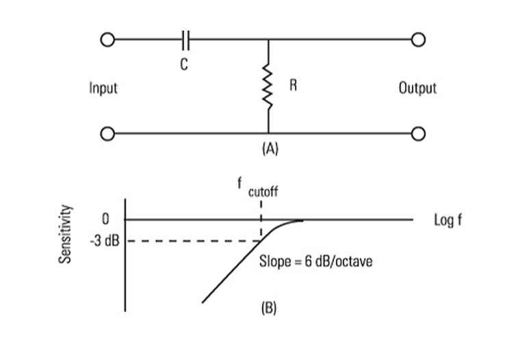
Figure 2 - Accelerometer Low Frequency Response
The “R” (resistance) and “C” (capacitance) values in Figure 2 combine to form the Discharge Time Constant (DTC) of the accelerometer. “R” and “C” are also built into the internal amplifier of the ICP® accelerometer. For the most extended low frequency response, one would choose the largest possible values for “R” and “C” (assuming no other negative effects).
However, it turns out that increasing the capacitance also decreases the effective sensitivity of the accelerometer. Also, maximizing the resistance increases electrical noise in the accelerometer, especially at low frequencies. As such, the effect of "R" and "C" also depend on whether it is a charge-amplified ICP sensor like a ceramic sensing element or a voltage-amplified ICP sensor like many quartz sensing elements. In a charge-amplified design, "C" is in the feedback loop of the internal amplifier and is used to set sensitivity, while "R" sets the time constant. In a voltage-amplified design, "C" is normally just the element plus input amplifier capacitance. Rarely is more capacitance added in parallel to reduce vibration sensitivity. This added capacitance for attenuation is normally only done in piezoelectric force and pressure sensor designs. Resistance value is still used to set the time constant in voltage-amplified designs.
The high frequency response of an (unfiltered) piezoelectric accelerometer is most often determined by the mechanical design of the sensing element. The high frequency of the accelerometer’s mounted resonant frequency response approximates a first-order high-pass filter, as shown in Figure 3.
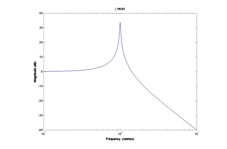
Figure 3 - Typical Second Order High Frequency Response
As a mechanical counterpart to the mathematical model, we use the spring-mass system of a shear mode accelerometer, Figure 4. The second order mass coefficient is the seismic mass, and the zero order spring coefficient is the stiffness of the piezoelectric material.
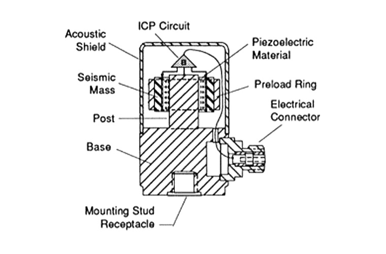
Figure 4 Accelerometer Low Frequency Response
If an application needs extended low frequency response, the accelerometer design usually increases the input capacitance of the ICP® electronics, reducing the sensitivity. This forces the accelerometer design to use a larger seismic mass for higher sensitivity, and increases the overall mass of the accelerometer, in addition to reducing the high frequency range.
To extend the high frequency range of an accelerometer, the seismic mass is reduced, which reduces the sensitivity.
The fortunate application reality is that test structures that require low (< 0.5 Hz) frequency range (such as civil engineering structures) are generally more massive, and can tolerate more massive accelerometers.