Main Menu
- Home
- Product Finder
- Calibration Systems
- Calibration Services
- Digital Sensing
- Industrial Vibration Calibration
- Modal and Vibration Testing
- Non-Destructive Testing
- Sound & Vibration Rental Program
- Learn
- About Us
- Contact Us
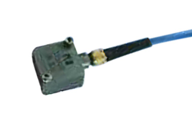
 Accelerometers are transducers that generate an electrical signal output as a result of a mechanical acceleration input to the unit. The most common type of accelerometer operates by the piezoelectric effect. Piezoelectric (PE) accelerometers
are generally classified in two groups – low impedance voltage mode (for example, PCB Piezotronics trademarked ICP®) or charge mode. Other types of accelerometer transduction methods include piezoresistive (PR), based upon strain gage
technology, and variable capacitive (VC).
Accelerometers are transducers that generate an electrical signal output as a result of a mechanical acceleration input to the unit. The most common type of accelerometer operates by the piezoelectric effect. Piezoelectric (PE) accelerometers
are generally classified in two groups – low impedance voltage mode (for example, PCB Piezotronics trademarked ICP®) or charge mode. Other types of accelerometer transduction methods include piezoresistive (PR), based upon strain gage
technology, and variable capacitive (VC).
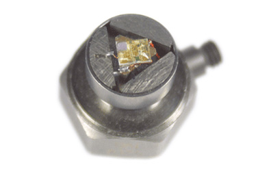
Found naturally in quartz and synthesized in special ceramics, the piezoelectric effect is the phenomenon that an electrical charge is produced as a result to a stress applied to the material. PE accelerometers utilize this technology by mounting an inertial mass to a piezoelectric crystal. When the sensing element experiences acceleration, this inertial mass applies force to the crystal which creates stress resulting in the output of an electrical charge. Collected on an electrode, the high impedance electrical charge signal can be conditioned by either internal or external electronics for measurement purposes. Accelerometers containing internal electronics are classified as Integrated Electronic PiezoElectric (IEPE), but commonly referred to by users as “voltage mode” accelerometers. Alternatively, PE accelerometers requiring external charge amplifiers for signal conditioning are called “charge mode” accelerometers.
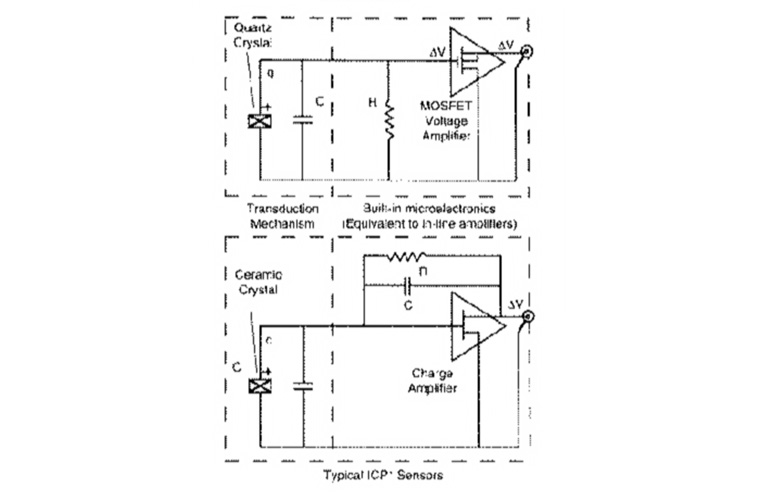
Voltage mode PE accelerometers incorporate built-in, signal conditioning micro-electronics. ICP®, as mentioned previously, is PCB Piezotronics’ registered trademark that stands for “Integrated Circuit Piezoelectric” and identifies IEPE accelerometers manufactured by PCB. PCB is credited as the company most responsible for development of this technology. ICP/IEPE has been adopted as the standard by the industry's sensor, analyzer and data acquisition manufacturers.
All of these voltage mode accelerometers are powered by a regulated DC voltage and 2 to 20 mA of constant current sensor excitation over a simple two wire scheme. The built-in electronics convert the high impedance charge signal generated by the piezoelectric material into a useable low impedance voltage signal right inside the transducer. Since the output is low impedance, the signal can be transmitted over long cable distances and used in dirty field or noisy factory environments with little degradation.
Charge mode PE accelerometers output the high impedance electrical charge signal generated directly from the piezoelectric sensing element. These transducers require an external charge amplifier or an in-line charge converter to convert the high impedance charge signal to a low impedance voltage signal suitable for measurement purposes. These devices utilize high input impedance, low output impedance inverting amplifiers with capacitive feedback. Adjusting the value of the feedback capacitor alters the transfer function and/or gain of the charge amplifier.
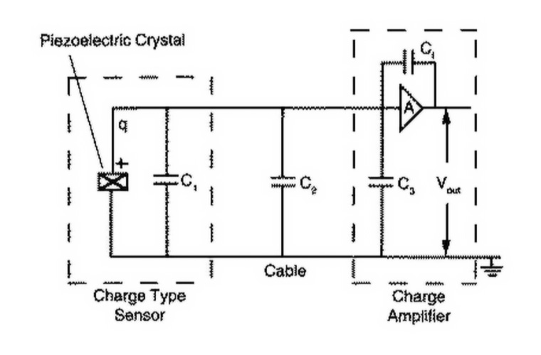
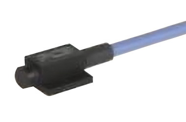
Since the output is high impedance, the charge signal is very sensitive to noise from the surrounding environment and several important precautionary measures should be taken for proper measurements. Special low noise coaxial cables should be used between the transducer and the external charge amplifier. These cables are specially treated (for example, lubricated with graphite) to reduce triboelectric, or motion induced, noise effects. Also, it is critical to maintain high insulation resistance of the transducer, cabling and connectors by keeping them dry and very clean. Given these precautions compared with the simple operation of voltage mode accelerometers, charge mode accelerometers are generally only used in high temperature applications (above 250 °F) where the voltage mode accelerometers internal electronics fail.
The last important characteristic of all PE transducers (voltage mode and charge mode alike) is their AC behavior. Piezoelectric material is unable to hold its charge output due to a static input. In other words it only senses dynamic events, and thus cannot be used to measure DC acceleration. The design of the charge amplifier electronics (whether integrated internal or external) define the low frequency AC couple of the measurement signal. With voltage mode accelerometers this is a fixed value. With charge mode, the external charge amplifier commonly allows the user to alter the settings to control the AC coupling. Typical low frequency performance of PE accelerometers ranges from ½ to several Hz.
 The second transduction method utilizes the piezoresistive effect. PR accelerometers are designed with sensing elements that change their electrical resistance due to an applied
mechanical stress. Unlike the self-generating PE sensing element, the PR accelerometer does not produce a charge signal but instead only has a varying resistance that must be measured as a varying voltage. PR accelerometers typically require
a fixed, DC excitation voltage ranging in value from 5 to 15 VDC.
The second transduction method utilizes the piezoresistive effect. PR accelerometers are designed with sensing elements that change their electrical resistance due to an applied
mechanical stress. Unlike the self-generating PE sensing element, the PR accelerometer does not produce a charge signal but instead only has a varying resistance that must be measured as a varying voltage. PR accelerometers typically require
a fixed, DC excitation voltage ranging in value from 5 to 15 VDC.
PR accelerometers utilize piezoresistive material, either metal strain gage or silicon resistors, in a Wheatstone bridge configuration. Elements are typically bonded to a cantilever beam that bends in response to acceleration, thus changing the resistance. This varying resistance responds to steady-state acceleration which allows PR accelerometers to provide a true DC response. This DC response allows for integration of the shock signal, and, coupled with low susceptibility to zero shift, is a primary reason that PR accelerometers are commonly used in crash test and shock applications.
 Lastly, variable capacitive (VC) accelerometers sense a change in electrical capacitance, with respect to acceleration, to vary the output of an energized circuit. The sensing
element design consists of two parallel plate capacitors acting in differential mode. These capacitors operate in a bridge circuit, along with two fixed capacitors, and alter peak voltage generated by an oscillator when the structure undergoes
acceleration. Detection circuits capture the peak voltage, which is then fed to a summing amplifier that processes the final output signal.
Lastly, variable capacitive (VC) accelerometers sense a change in electrical capacitance, with respect to acceleration, to vary the output of an energized circuit. The sensing
element design consists of two parallel plate capacitors acting in differential mode. These capacitors operate in a bridge circuit, along with two fixed capacitors, and alter peak voltage generated by an oscillator when the structure undergoes
acceleration. Detection circuits capture the peak voltage, which is then fed to a summing amplifier that processes the final output signal.
VC accelerometers, like PR accelerometers, typically operate on a four wire system, one pair of wires for signal/ground and another pair for power/ground. The excitation voltage required is typically a fixed, DC voltage ranging from 10 to 30 VDC, depending on specific model and manufacturer.
Most examples above describe the assembly of transducers from the mechanical bonding of discrete components, which generally are manually assembled, one at a time. However, some manufacturers use techniques borrowed from semiconductor manufacturing to make mass-produced monolithic sensors from silicon. The characteristics of PR and VC devices, in particular, are well suited to miniaturization. The result is referred to as MEMS, MicroElectroMechanicalSystems.
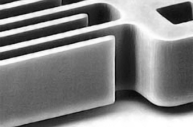 Mechanically useful shapes in silicon can be created using mass removal techniques exploiting the crystallography of silicon and chemical etchants that usefully etch single crystal silicon
in primarily one direction only, in microscopic patterns defined by masks used in the industry. Additionally, the powerful etching equipment in the semiconductor industry provide precise material removal with microscopic dimensions. This capability,
plus the convenient fact that resistors implanted in silicon along crystallographic directions are by nature piezoresistive, allows an entire full bridge strain gauge transducer to be created with dimensions on the order of a millimeter.
Mechanically useful shapes in silicon can be created using mass removal techniques exploiting the crystallography of silicon and chemical etchants that usefully etch single crystal silicon
in primarily one direction only, in microscopic patterns defined by masks used in the industry. Additionally, the powerful etching equipment in the semiconductor industry provide precise material removal with microscopic dimensions. This capability,
plus the convenient fact that resistors implanted in silicon along crystallographic directions are by nature piezoresistive, allows an entire full bridge strain gauge transducer to be created with dimensions on the order of a millimeter.
Single crystal silicon is extraordinarily strong. And, iIllustrated by the impressive feats of strength of ants which lift many times their own weight with tiny bodies, the physics of the strength of materials means there can be great advantages in the overall performance through miniaturization. Damping is another example of the advantage of small size, since at dimensions on the order of a wavelength of light even fluids as inviscid as air can provide useful damping forces. Compared to the extremely limited temperature spans of liquid damping, air damping exhibits nearly no change with temperature.
VC devices can also be created with similar structuring of the cantilevers into flat plate capacitors, and benefit from the same air damping to tune response to maximal-bandwidth critical damping. Generally the active element is protected in a sandwich of layers that create a rugged monolithic assembly that can be treated as an electrical component in hybrid microelectronics.