Main Menu
- Home
- Product Finder
- Calibration Systems
- Calibration Services
- Digital Sensing
- Industrial Vibration Calibration
- Modal and Vibration Testing
- Non-Destructive Testing
- Sound & Vibration Rental Program
- Learn
- About Us
- Contact Us
Pressure Calibration Methodology
Dynamic pressure sensors are typically calibrated by varying the amplitude, rather than the frequency, of the physical input. It so happens that the physics of building a controlled actuator that covers the dynamic range of piezoelectric and piezoresistive pressure sensors is, in a word, challenging. As a result, multiple dynamic pressure calibration techniques have been developed, which is the subject of this month's article.
Dynamic Pressure Calibration
Of the many pressure sensor designs available, two stand out for their excellence in measuring dynamic, rather than static, pressure. Piezoelectric pressure sensors excel at high frequencies and pressure levels and are inherently rugged for the most demanding environments. Condenser microphones offer unparalleled sensitivity for acoustic measurements. Since these two designs are uniquely suited for dynamic measurements, the best calibration techniques for them require a dynamic, rather than static, input.
Dynamic calibration inputs are classified as periodic (steady state and repeating) or aperiodic (transient). The dynamic calibration input (periodic or aperiodic) should be chosen such that it calibrates the sensor in a way that is similar to the sensor’s field application. Of course, physical limitations may also apply, but in general, periodic signals are used to calibrate high-sensitivity acoustic microphones, and aperiodic techniques are used to calibrate low-sensitivity pressure sensors. For the purposes of this article, we will discuss aperiodic techniques.
Step Input
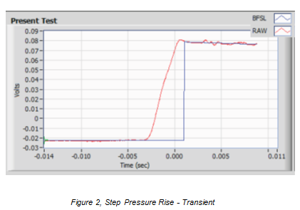
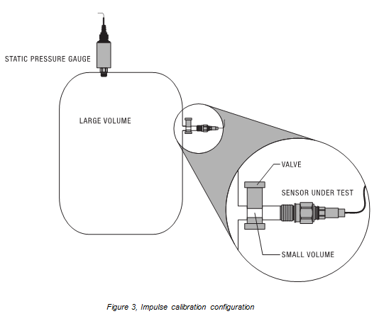
Step Inputs provide a quick rise in pressure to the sensor under test. As shown in Figure 3, the pressure rise is created by first pressurizing a large volume of gas and measuring the pressure very precisely using a static pressure gauge. This large pressurized volume is released into a very small volume wherein the sensor under test is mounted. The voltage output rise of the sensor under test is measured. The drop in pressure of the combined volume due to the gas expansion is known to be very small, and it is included in the estimate of measurement uncertainty. Errors due to acoustic resonances and long-term signal decay effects are compensated using signal processing, resulting in the synthesized step response (blue curve) in Figure 2. The output of the sensor is then normalized by the reference pressure to calculate the sensitivity of the sensor under test.
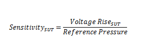
Figure 1, Calculating the sensor sensitivity for the 'step' calibration input.
Impulse Input
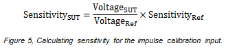
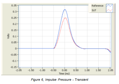
Impulse inputs provide a quick rise and fall of the pressure level. A sensor under test and a reference sensor are mounted very closely in a closed volume of oil. A third port on the volume is occupied by a piston. The piston is struck on the outside of the volume, which applies a force to the oil creating a pressure impulse that is simultaneously observed and measured by the two sensors.
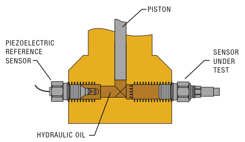
The instantaneous peak voltage output of both the sensor under test and the piezoelectric reference sensor are recorded. The sensitivity of the reference sensor is known. These three values (two voltage measurements and reference sensitivity) are used to calculate the sensitivity of the sensor under test.