Main Menu
- Home
- Product Finder
- Calibration Systems
- Calibration Services
- Digital Sensing
- Industrial Vibration Calibration
- Modal and Vibration Testing
- Non-Destructive Testing
- Sound & Vibration Rental Program
- Learn
- About Us
- Contact Us
Nothing is more frustrating than making an on-site vibration measurement and having the data just not "look right." The test could be complex like a large-scale modal survey on an aerospace structure, or hardwired to automate like the 4-20 ma current loop output accelerometer running into a machine supervisory control system. Regardless, when data is looking sour, it is extremely helpful to get back to a known output with a field method of vibration calibration or verification. We will look at three quick and easy methods to validate your accelerometer on the go. The first two are extremely simple and cost-effective using only gravity, and the third, while more involved, is still quick, portable and provides the added benefit of selectable frequencies for input and validation.
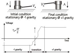
First, let’s identify what type of accelerometer you are using. If it has a static or DC response, then it is likely it operates under the characteristics of a Piezoresistive (PR) or Variable Capacitance (VC) vibration sensing element. Typically, these can be commonly MEMS (silicon wafer etched with “Micro Electro Mechanical Structures”) or discrete hand-fabricated sensing elements. With a DC responding vibration sensor, verification is as easy as flipping the unit over. This creates a 2 g swing in the sensor's output from +1 g right-side up to -1 g up-side down. The measured step output can then be divided in half to validate the proper 1 g scaling of the DC response accelerometer.

More commonly, both structural and industrial vibration measurements call for more dynamic range than is typically found in a MEMS accelerometer. Instead, the vibration sensing element is constructed with a mass loaded crystal employing the piezoelectric effect. These piezoelectric (PE) accelerometers can be structured with no internal electronics (charge output) coupled to a laboratory-grade charge amplifier for signal conditioning and impedance conversion to low-impedance voltage output. It can also be coupled with integrated circuit piezoelectric electronics (ICP®) to accomplish the impedance conversion economically and simply, sealed within the sensor housing requiring modest excitation voltage power through a constant current diode.
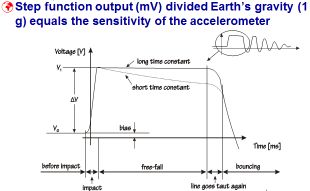
Both methods are AC-responding measurement systems with a Discharge Time Constant (DTC) and cannot be calibrated by the relatively slow flip test described above. For these dynamic responding vibration sensors, we use a simplified drop test fixture which allows for static suspension and then rapid free fall in Earth’s gravity. The resulting step function output of the vibration sensor can be directly scaled to the 1 g change in gravity from static suspension (-1 g) to free-fall (0 g). While supplying a direct scale factor, this method still does not provide any frequency reference.

The final method of dynamic field testing of the complete vibration measurement channel is with a portable vibration excitation source using known output. This can be accomplished with either a simple 1 g single frequency hand-held vibration calibrator for validation level uncertainties or a precision portable vibration calibrator for a variable g-level selection and broad frequency range--both designed to perform calibration level uncertainties. In this last case, the vibration sensor can be calibrated at various g levels to ensure linearity (and uncover signal condition problems like clipping) as well as validating at low-, mid- and high-excitation frequencies (and validate DTC/low-frequency performance, mounting and mechanical integrity).
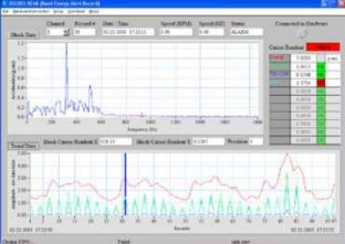
An added benefit of a precision selectable vibration level calibrator allows for in-place verification of whole channel vibration alert and alarm levels (often set in either ips or g’s).

In the end, your measurement integrity comes down to control and confidence in your vibration sensing channel. These methods each can help you establish proper operation and verify calibrated output levels to ensure your confidence. Let us know if you have more questions regarding field ready vibration calibration methods, and we will be glad to help.